Haverstraw Water Treatment Plant
United Water New York (UWNY), a provider of water and wastewater services in the US, has proposed a water supply project
Trending:
United Water New York (UWNY), a provider of water and wastewater services in the US, has proposed a water supply project
United Water New York (UWNY), a provider of water and wastewater services in the US,...
Read More...
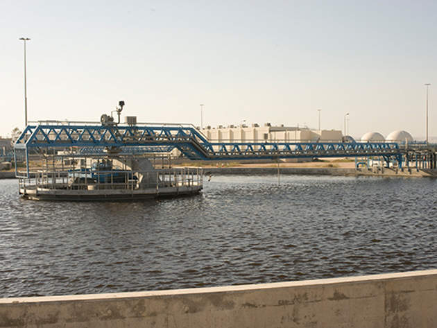
The largest wastewater treatment facility in Jordan, the As-Samra wastewater treatment plant (WWTP) was built...
Read More...
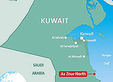
Phase I of the Az-Zour North Independent Water and Power Project (IWPP) is located at...
Read More...
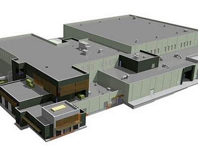
Colorado Springs Utilities constructed a new water treatment plant in El Paso County, Colorado, US,...
Read More...
The Xiluodu double-curvature arch dam was built by China Three Gorges Corporation (CTGPC). It is...
Read More...
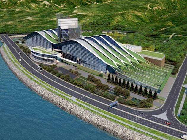
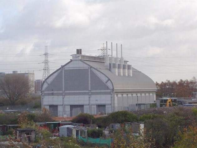
The Hong Kong Government's Environmental Protection Department (EPD) embarked on a major project to construct...
Read More...
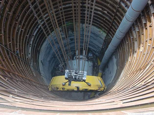
The Lee Tunnel project is the first of the two tunnelling projects executed as part...
Read More...
The Euclid Creek Storage Tunnel Project forms a major component of the Northeast Ohio Regional...
Read More...
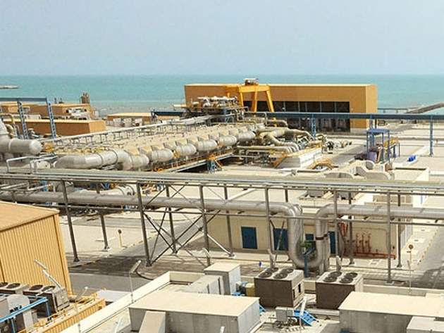
Ras Abu Fontas (RAF) A2 Seawater Desalination Plant is located at Ras Abu Fontas, about...
Read More...
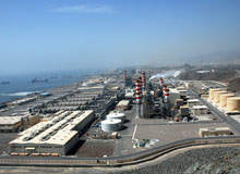
Fujairah 1 Independent Water and Power Plant is a hybrid desalination plant incorporating multistage flash...
Read More...