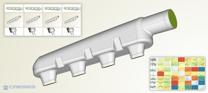
A new version of FRIENDSHIP SYSTEMS AG geometry modelling and optimisation software, CAESES® 4.4, has been released. The solution targets CAD and simulation engineers.
New help system in CAESES 4.4
CAESES® 4.4 comes with a large set of enhancements and new capabilities for an easier use and a faster start with CAESES. Beginners can now use a new help system that centralizes all documentation, and that makes things much easier to find.
Robust Boolean Operations and filleting for complex geometries
The entire geometry engine of CAESES® has been improved to provide faster and more robust geometry operations such as Boolean Operations and filleting. This effort continues to make sure that the geometries of complex models do not break or fail to regenerate within automated design studies.
The rendering and navigation (zoom, rotation, translation) in the 3D view have been accelerated. By using a completely new approach to render and visualize the data, the performance of the 3D view is now able to work with large amounts of rendering data.
Transparent visualisation of non-selected geometries
When selecting an object (e.g. point, curve, surface) in the tree or in the 3D view, all other objects are set to transparent. As a result, it is much easier to detect which object is selected, and investigating the whole model is also easier now.
Create a smooth patch with derivative information from adjacent surfaces
With version 4.4, users can consider derivative information from the adjacent surfaces when creating a Coons Patch or Lofted Surfaces. The Coons Patch automatically computes the derivatives based on the input surface curves and generates a smooth transition to adjacent surfaces.
Assign colour and triangulation settings for each individual surface patch
One major highlight of the new version is the individual patch processing for BReps (Boundary Representations) as a one-time pre-processing step for all variants. Users can override the global settings for the colour identifier and the triangulation of each patch. Just choose the edit mode of the BRep, select a patch and apply individual settings. All these settings are propagated down to the exported STL file. This means that even subsequent operations (add sources, trimming, filleting, intersections, etc.) will maintain these settings.
Users can still use global tolerances for the triangulation accuracy and the colours, but the individual local setting will still be there. As a result, users have more control and a higher accuracy for critical, highly curved regions while not substantially increasing the total amount of data.
New healing options to automatically repair imported geometries on a NURBS basis
Some new healing options are now also part of the BRep object. These healing options fix the topology of “unclean” BReps by internally applying snapping mechanisms. “Unclean” means that corners or edges of adjacent geometry patches do not coincide exactly even though it looks like they are matching, as long as users do not heavily zoom into the details.
Such numerical artefacts have been observed in imported files from other CAD systems. In particular, and as a request from maritime customers, the new healing capabilities work well for ship hull geometries that are exported by the NAPA software.
Only a single click for frequently used display options
Some of the frequently used display options received a separate icon for faster access. This includes displaying the control net of the underlying NURBS representation for curves, surfaces and BReps as well as visualisation of BRep edges (open edges vs all edges using red/green colours). There is also the new option to show the edges of a BRep in a grey colour, e.g. for nicer screenshots and animations.
Assign colours in CAESES with specific names to prepare the ANSYS “Named Selections”
The CAESES® geometry engine, to integrate CAESES® into the ANSYS Workbench, has been updated where a major feature could be added. In the previous version, the surface colours were transferred with their colour codes, i.e., the colour codes appeared as the Named Selections. In this new version, the name that users set in CAESES® finally shows up in the user interface of the ANSYS Worbench.
If users tag one of the surfaces as e.g. “io_inlet” (through creating a colour with this name), this name will appear again as the Named Selection. In addition, users can also manipulate the geometry in the ANSYS DesignModeler, and the automation will still work, which was not possible with the previous CAESES® app.
Easy-to-use CAESES integration in Optimus
Finally, the connection between CAESES® and the Noesis software solution Optimus has been further improved to integrate CAESES® much easier into the user interface of Optimus. Optimus simply needs the control file (*.fsc) for the batch mode run of CAESES® and will then show all design variables along with their lower and upper bounds. There is also a CAESES® icon in the Optimus user interface that can be dragged into the Optimus workspace.


